Parts Preparation#
Electronics#
Airscope Electronics#
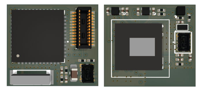
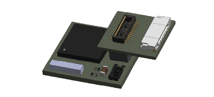
Main PCB#
The main PCB is the central electronics board of the Airscope. It hosts the image sensor, ESP32 microcontroller, onboard antenna, LED driver, and connectors to the auxiliary boards.
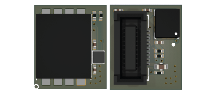
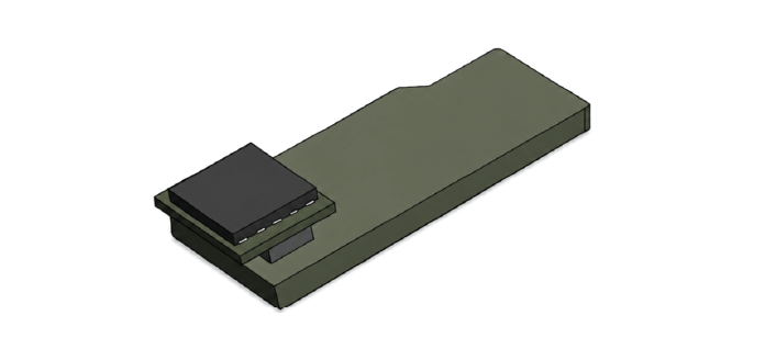
Extension PCB#
The extension PCB connects to the main PCB through a board-to-board connector. It provides local data storage using an SD NAND chip to minimize the overall size, and also includes inertial sensors for motion recording. If you want to extend the functionality of Airscope, you can add components to the extension board without having to change the main PCB.
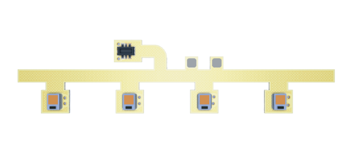
LED FPC#
The LED FPC is a flexible illumination board carrying the blue excitation LEDs. It is routed along the side of the housing so that each LED is positioned in its designed illumination slot. The LED FPC connects to the main PCB through a board-to-board connector.
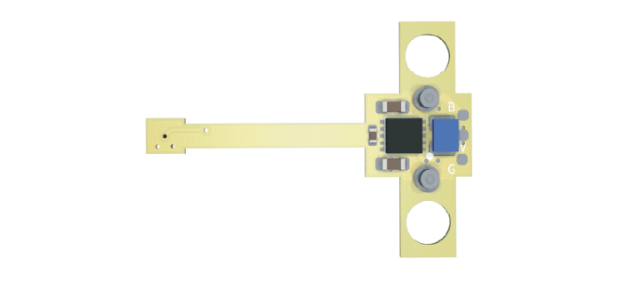
Power FPC#
The Power FPC connects the battery to the Airscope electronics. It supports a snap-on design for rapid battery attachment and replacement during experiments. The battery is mechanically secured with magnets and electrically connected through pogo-pin contacts.
Auxiliary Electronics#
Flash PCB#
The Flash PCB is used for programming the Airscope firmware and monitoring the serial output during debugging.
SD Card Converter PCB#
The SD card converter PCB converts the Extension PCB interface to a standard SD card interface, allowing the recorded data to be read from a computer.
Getting the Electronics#
All Airscope PCBs are based on off-the-shelf electronic components and can be fabricated by standard PCB manufacturers. We have been using JLCPCB to fabricate the PCBs and FPCs. All fabrication-related files can be found in the GitHub repo.
Optics#
Aspheric Lens Module#
The Airscope optical module uses a compact aspheric lens assembly. This module forms the main imaging path and is press-fitted into the top opening of the housing.
Excitation Filters#
The excitation filters narrow the excitation LED spectrum and help prevent excitation leakage and optical crosstalk.
Item |
Specification |
|---|---|
Type |
Bandpass excitation filter |
Size |
2 × 2 × 0.5 mm³ |
Wavelength range |
440–477 nm |
Quantity |
4 |
Emission Filter#
The emission filter blocks excitation leakage and passes fluorescence emission to the image sensor.
Item |
Specification |
|---|---|
Type |
Bandpass emission filter |
Size |
4 × 4 × 0.5 mm³ |
Wavelength range |
505–560 nm |
Quantity |
1 |
Getting the Optics#
The Lens Module is fabricated by Sunny Optics, with the Zemax file provided in the repo. Please contact the authors if you need help obtaining the lens.
The emission filters can be ordered from most filter vendors, such as Chroma. Just send the specifications, including the size and wavelength range.
Mechanical Parts#
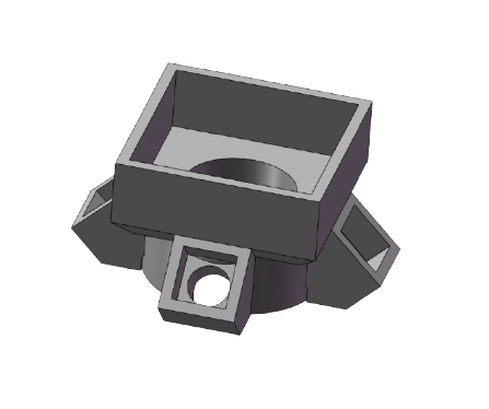
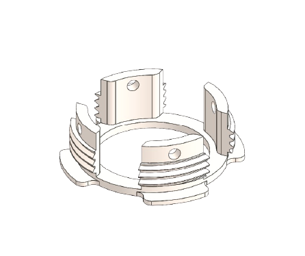
Housing#
The Airscope housing holds the lens module, optical filters, LED FPC, and PCB stack in fixed alignment. The housing is 3D printed using black resin to reduce stray light.
Baseplates#
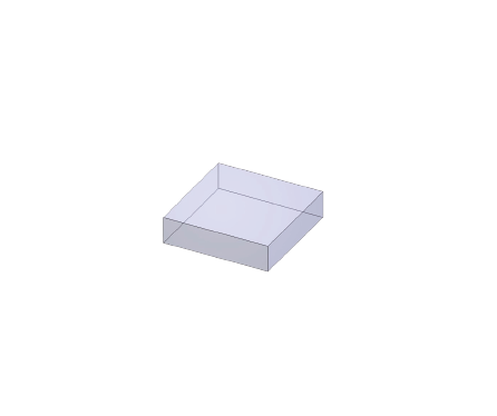
Spacer-Based Version#
Baseplate v1#
In this version, the focal plane is adjusted by inserting a spacer of defined thickness between the Airscope housing and the baseplate. The Airscope is then fastened with screws.
Spacers#
Spacers are used to fix the focal plane. Use a 0.05 mm step size to find the best focus for each preparation.
Rotary Focusing Version#
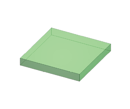
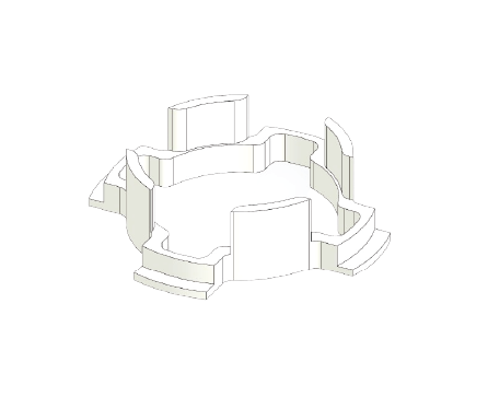
Baseplate v2#
The baseplate holds the Airscope and supports the rotary focusing parts.
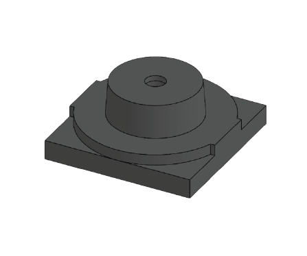
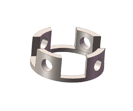
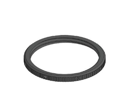
Focus Ring#
The focus ring is rotated to adjust the focal plane.
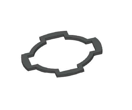
Locking Ring#
The locking ring fixes the Airscope at the selected position.
Getting the Mechanical Parts#
The housing and spacers in Baseplate v1 can be printed with an SLA 3D printer.
[Form 4 printing instruction and one-click printing file] We have been using the Formlabs Form 4 to print all the parts. During printing, the size of the slots needs to be adjusted to allow a perfect fit; normally, increasing the size by 0.1 mm works. The support also needs to be generated on the correct side to ensure the surface quality of essential surfaces. The adjusted-size parts and PreForm fabrication files are included in the GitHub repo for one-click fabrication. After printing, wash and cure the parts following the regular Formlabs post-processing protocol. Grind the bottom side of the housing to ensure it is flat before assembly.
It may also be possible to fabricate the parts with other resin printers (e.g. HeyGears), though we have not tested this. You can also outsource fabrication to an online 3D printing service (e.g. Protolabs).
The baseplate is CNC machined from Alumin. Please send the fabrication files in the GitHub repo to a machine shop to have it made.
Assembly Materials and Tools#
Prepare the following materials and tools before starting the Airscope assembly.
Item |
Type |
Notes |
|---|---|---|
M1.5 × 1 mm screw |
Structure |
Used to fix the focus in the spacer-based version |
3 mm magnet |
Structure |
Used for the snap-and-go battery connection; 1 mm thick |
100 mAh battery |
Electronics |
Used to power the Airscope during wireless recording |
Battery charger |
Electronics |
Charges the battery |
Multimeter |
Electronics |
Used to check voltage and resistance |
SD reader |
Electronics |
USB SD reader for reading the data |
UV-curable optical adhesive |
Assembly |
Used to fix filters, LED FPC, housing, and mechanical contact points. We have been using Ergo UV glue. |
UV curing lamp |
Assembly |
Used to cure optical adhesive after alignment |
Fine applicator / needle tip |
Assembly |
Used to apply small amounts of adhesive precisely |
Fine tweezers |
Assembly |
Used to handle filters, FPCs, and small mechanical parts |
Gloves |
Assembly |
Used to handle optical and electronic components |
Lens paper / optical wipes |
Assembly |
Used to clean filters and lens surfaces |
Dust blower |
Assembly |
Used to remove loose dust from optics and the sensor area |